|
Other Avayanic Web Sites |
||||
|
 |
|
| [R2D2] [Dream] [History] [Collection] [Electronics] [First Walk] [Tools] |
|
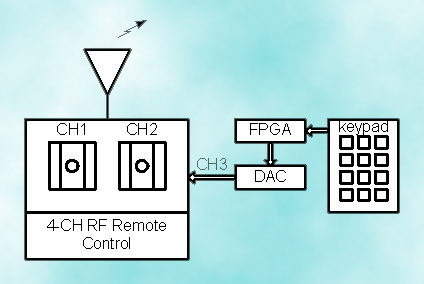
"Uncle Owen, this R2 unit has a bad motivator. Look!" Oh! At least! When I began constructing an R2D2, one of the main reasons was having something to fill with electronic gadgets. R2D2 is not the most efficient form of droid mechanics. In fact, although on the movies he looks wonderful, he was a pain while filming. And that was only an ornamental R2D2 so imagine a real R2D2 capable of doing real tasks such as cleaning (somehow everybody wants my R2 to do this...) or fixing a ship (???). I have desisted of the idea of filling my R2D2 with electronic gadgets since it is not cost efficient neither very practical when analyzed from an engineering point of view. Still making him walk was a challenge! Recall that most of my "friends" wanted to tie R2D2 to their car bumper so that he could move! It just became personal! So I devised a way to control R2's movements by using a commercially available 4 channel airplane remote control. Why 4 channels? Because with two channels I can only control the motors on both legs. To control other neet things such as sounds, doors, arms and lights I need more channels. In this page it is explained how the electronics enabled me to control most of R2D2's functions. The block diagram for most of R2D2 electronics are shown below:
R2D2 Transmitter Block Diagram
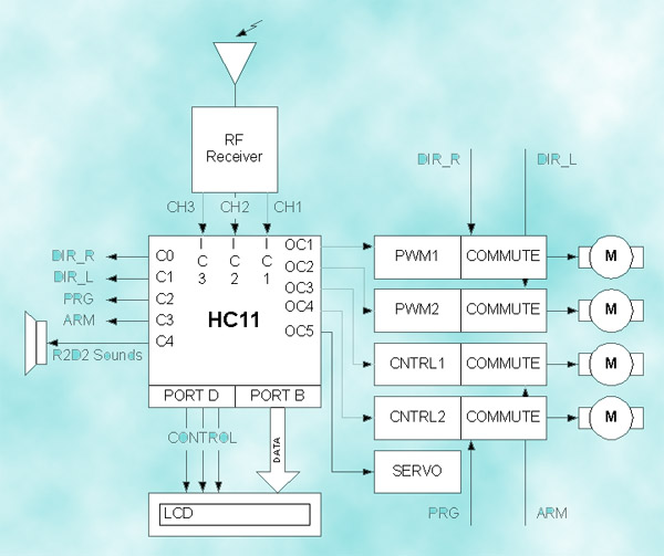
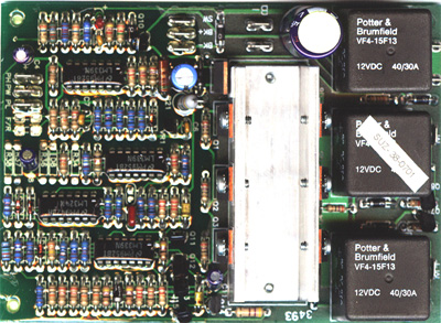
R2D2 Receiver Block Diagram The actual circuit inside R2D2 is the Receiver Block Diagram. It is based on a microcontroller from Motorola: the M68HC11A8. This MCU was selected because of its ease of use and because I have actually become an expert using this platform while teaching Microprocessor Interfacing at the University of Puerto Rico, RUM, Electrical Engineering Department. I also have accessible the tools necessary to develop applications based on this MCU. Just after I began the design stage, I took a seminar on the HC12 which is a more powerfull version of the HC11 family of Motorola MCU's. I even have the development tools necessary to work with the HC12, but working with the HC11 was more challenging since it involved more designing to do (with the HC12 it would have been almost like plug and playing and I was trying to get some fun!!!) On this page you will not find any information on how the HC11 works since it takes quite a while (and a bunch of books) to learn how to use it. If you want to learn how to use this powerful tool I suggest buying books such as Miller's Microcomputer Engineering, Cady's Software and Hardware Engineering and Skroder's Using the M68HC11 Microcontroller. They are all available from http://www.amazon.com Books on the net. A few years later from this web site being generated for the first time , I compiled my own HC11 page on a place I called MCUMaster. It is still online on HC11. Also, the code for this application can be found at the end of this page. OK! Lets get to business. First lets get out of the picture the transmitter which is really nothing but an RF transmitter sending a Pulse Width Modulated signal. Three of the four channels will be used. The first two channels are the sticks used to change the resistance on the potentiometers inside the control. This potentiometers divide the voltage that is being feed into the transmitter. The voltage magnitude will determine the pulse width of the signal to be sent. The PWM signal used in all remote control applications (which is fed to speed control circuits and servos) consists of a 1 ms to 2 ms pulse width. To a servo, 1.5 ms means center, 1 ms means full left and 2 ms means full right. Intermediate values provide different ranges of movement. In my R2D2 leg motors 1ms means full reverse, 1.5ms means stop and 2ms means full forward. This is the typical speed control circuit scenario. RC cars sold everywhere use this signal in this way to determine if they are going forward or backward and how fast. RC cars use an analog circuit to change the PWM into speed and direction. Since I am an Electrical Engineer with specialization in Digital Electronics I decided to go for the digital approach! The Receiver circuit is the RF receiver that comes with the remote control. At first I tried to build it but working with RF is very tedious and too many things have to be taken into account. You could interfere with other operating devices on the neighboring areas and that is something the FCC does not likes very much. The output of this receiver is the PWM signal explained below. Since the voltage levels of the signals are TTL compatible (0 volts for logic low and 5 volts for logic high), the receiver outputs can be connected directly into the MCU inputs. Now let me explain the theory involved in speed control using an MCU. The HC11 (as well as so many other MCU's) is powered with a timer circuit that enables the designer to measure with precision the time elapsed between rising and falling edges in an incoming signal. This function is called the Input Capture. Once I have the time elapsed between rising and falling (the pulse width) I can determine if it is lower or higher than 1.5ms. This determines the direction right away. Speed is determined by calculating the difference between 2 ms and the time measured. If reverse direction was found, the difference is between time measured and 1 ms. Along with the Input Capture function, the timer unit allows the opposite. This other funtion is called Output Compare and it consists of generating square wave signals by allowing the output to go high or low whenever a match is found on a register and the timer itself. More information about this neat features is provided in the PROGRAMMING page. Speed and direction are determined and a new PWM signal is generated (using Output Compares). Why a new one? The PWM used in RC applications is not capable of achieving a 100% duty cycle. That is, there is no way the signal will remain logic high during the whole period. But the circuit which will actually determine the speed (voltage applied to the motor) is a Buck converter. Buck converters limit the voltage across its output terminals according to the duty cycle. If the duty cycle is low, voltage output is low and vice versa. The higher output voltage the Buck converter can supply is a couple of milli volts lower than the voltage supplied to its input terminals. The HC11 will supply a 500 Hz signal that can be fully modulated. This signal will be transformed into a voltage differential according to its duty cycle. The motor rotates at a speed proportional to the voltage applied to its terminals. But to manipulate direction a voltage commutator has to be used. A voltage commutator is simply a circuit that interchanges the polarity applied to a pair of terminals. It can be implemented with relays but since they are so slow (and I love electronics) I decided to go for the typical H-Bridge configuration. At the time I decided to implement my own H Bridges. This is no easy task, which resulted in many burnt transistors. Hence I decided to purchase two wheel chair large DC motor controllers as can be seen below. I bought this on a place called Diverse Electronics. I am not certain whether they are still on business, but controllers like these are still widely available on the web.
Other electronic features are as follow. A servo is connected to an Output Compare. This servo is used to open the door. Two small DC motors are used to raise or lower the programming arm and the other to turn clockwise or counterclockwise the programming head. An LCD is provided for monitoring stages of operation. A sound board (taken out of an R2D2 toy) is connected to a control signal for activation. I have decided to merge the code and electronics page into one. |
|
"Always two there are: A Microprocessor and a Program!" It is amazing that I am writing this page almost 10 years after I said it was under Heavy Construction. Talk about Heavy! To be honest, all I can do at this moment is post the source code I used back then in 1998. It would take me hours (possibly days) to remember what I was doing back then. The way I code has changed quite a bit! Hence, reading my own 1998 code could cause brain hemorrhage or some form of epileptic attack. You, on the other hand, may find the downloadable zip to be useful, specially if you are wanting to learn anything on the now defunct HC11. My recommendation? Go with a newer microcontroller like the HC08 or HC12 (whatever variant is newer). In fact, rather than going with Motorola parts, I would choose MSP430’s AVR’s or even the PIC (which for purely personal reasons I hate, while others love). All of these architectures are better suited for beginners or even experts with a low budget. But if you want to stay with Motorols, start playing the Lottery so that you can buy the humongously expensive and hard to find development tools. Without a further adieu, here is the code! |
| [R2D2] [1997's] [200x's] [Current] [Accidents] |
|
|
|||||
|
|
|||||


